Quantcast
Channel: RetroFixes
Viewing all 54 articles
Browse latest View live

Intellivision Composite A/V Mod Kit Installation Guide

$
0
0


This tutorial will show you how to install the Intellivision Composite A/V Mod Kit 


Kit can be Purchased here.

Kit Details:

Kit PROS: This kit is the most compatible with a wide range of Intellivision motherboard variations. No components are permanently removed during the installation. It's easy for the average DIY hobbiest. Other upgrade kit designs (with equal video quality) require complete removal of RF unit, very difficult for most home DIY installers. With this kit only 4 wires are soldered to the motherboard.  The kit can be easily removed and reverted back to original RF if desired.

Kit CONS: As with all circuits I have tested the composite video is not perfect. You may see faint vertical lines on solid colors and some faint noise on screen.  I uploaded a few screen shots of games with this installed mod on my store page.  Keep in mind I have a very high standard with video quality and can be picker than most. For the cost and ease of installation this is a excellent kit.

Instructions are 99% complete. Some of the steps and grammar might be "off"

Disclaimer:
Though this job is a pretty easy task, it requires that you do some soldering of some wires and connections. If you are not skilled with a soldering iron, please send your console here for a full upgrade service! I cannot be held responsible for any harm you do to yourself or to your game console.

Before Starting.
Please leave your Intellivision game console at the ON position for at least 30 minutes with the power cord unplugged.. Please do not skip this stage! These consoles have large capacitors inside and they need to be discharged before doing any repairs/upgrades. Otherwise, you may get shocked by accidentally or unintentionally touching them


Tools Needed
• Soldering iron, solder, and solder braid
• X-Acto knife
• Drill with 3mm and 1/4” drill bits
• Needle-nose pliers
• Philips-head and flat-head screwdrivers
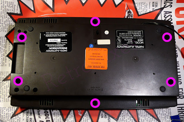
 
Step 1: 
Start by removing the 6 screws loacted on the bottom as shown below.


Step 2:
Again, unscrew the six screws off the platform housing the cables of Intellivision controllers. Follow the pink circles for location.  


Step 3:
Carefully unplug the controller plugs, ribbon and power wires. It’s highly recommended that you unplug everything very carefully, the ribbon and cables are fragile from age.


 After the cables are unplugged you can remove the motherboard unit from the console shell.


 Step 4 :  Now we need to removed the RF shielding. This step requires patience and is the most difficult step with the installation process. As shown below the top and bottom RF shield is held together by several soldered tabs. 


Several methods can be tried.  
Method 1. Use a desolder gun or desolder wick braid and remove the solder this will release the tabs. Method 2. Heat each tab with soldering iron and pry tab upwards with a xacto blade, as the solder releases the tab will break loose.  
Method 3. Cut the tabs off with metal cutters. Works and is fast but reinstalling the RF shielding might be difficult afterwards.
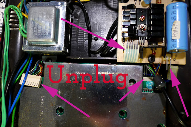


Step 5:
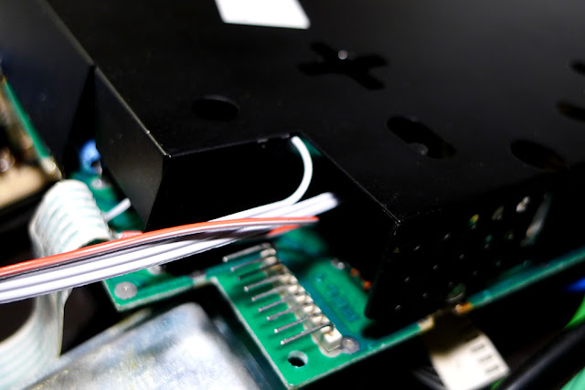
Next, we can start soldering the composite kit wires to the locations shown below. Look for these areas near the large metal RF box.


These solder points will connect to the input side of the upgrade kit.
Audio and video sources are found near the RF box as shown. Ground and power are located at the base of the ribbon as shown. The ribbon has 5 traces/stripes.  Trace 1 is power/5v and trace 4 is  ground.

Kit Pinout: 
(Input Side) Connections for Console Motherboard
AI=Audio In  / VI=Video In  / 5v=Power Input  /  G=Ground


Step 6:
Use your needle-nose pliers and bend the piece of metal at the black shielding as shown below. This will be our opening for the amp wires to pass through.


Step 7:
Now, solder back both of the RF shielding plates and make sure your previously soldered inner wires are not smashed in anyway. Your result for this stage should look something similar to the one below.


Step 8:
Drilling holes for RCA jacks.  I prefer installing jacks on the left hand side of the console. 15mm down from top edge and 15mm spacing between each hole.   Drill a small 3mm pilot first, then drill the final 1/4" holes.

Install the RCA jacks with the grounds tabs and lock washer on the inside of the shell. Tighten the jacks and add a small drop of crazyglue to the inside threads prevent loosening.


Step 9:
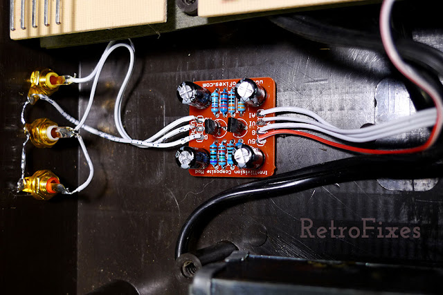
Solder wires to RCA jacks.
(Output Side) Connections to RCA Jacks
G=Ground, Connects to tabs on each RCA jack
VO=Composite Video Out, connects to yellow RCA jack.
AO=Audio Out, connects to both red and white RCA jack.


Step 10:
Now it's time to assemble your console and test your mod install. Make sure to reattach the power wires, controller wires and ribbon coming from the motherboard. Attach your double-sided tape on the back of the kit and place as shown in photo.


Testing:
If your mod doesn’t work, go back and double-check your wiring. 
Also make sure our games and  cartridge port are clean.

Magnavox Odyssey 2 AV Composite Kit Installation Guide

$
0
0


Why Upgrade?
The original system system had poor RF video quality. Many new HDTVs will not recognize vintage RF video signals. With this upgrade your sound and video will be much more crisp and clear.

Purchase the Kit Here.


Disclaimer:
Though this job is a pretty easy task, it requires that you do some soldering of some wires and connections. If you are not skilled with a soldering iron, please send your console here for a full upgrade service! I cannot be held responsible for any harm you do to yourself or to your game console. Please contact us for installation services if in doubt.

Before Starting.
Please leave your console system at the ON position for at least 30 minutes with the power cord unplugged.. Please do not skip this stage! These consoles have large capacitors inside and they need to be discharged before doing any repairs/upgrades. Otherwise, you may get shocked by accidentally or unintentionally touching them

Read this Awesome "Soldering is Easy – Comic" for Basic 101s of soldering click here.


Tools:
• Drill with 1/4” & 3mm drill bit
• Ruler
• Marker
• Soldering iron, solder, and solder braid
• X-Acto knife (optional)
• Needle-nose pliers
• Flat head screw driver (Adjustable wrench needed on some models)


Installation:

First,
Turn the console over and remove the 3 screws (or bolts). I have seen several different variations with the console.  Separate the halves gently and carefully.


Most models will have the metal RF shielding as shown below (if not lucky you).  De-soldering and removing this shield can be challenging


Before we can remove the RF shielding make sure to unplug all the input controllers, power cable and rf box. The old cables can be fragile, do not force anything.  Note: The large RF box as shown in lower left corner can be removed and discarded.  If you leave it in-place do not plug it in after upgrade.


Also be careful with the old vintage ribbon as shown below.  On most models it is easy to unplug. If you decide to leave it plugged be very careful while desoldering the RF shielding.

Desoldering Tip:
The RF shielding is held by several surrounding solder points.
I find it much easier to heat the old solder while simultaneously lifting the shielding as shown below. Do this for each tab surrounding the motherboard


Step 5:
Once the shielding is removed we can solder in the kit. The soldering area is highlighted by the pink outline.


Next solder the included wire to the amp kit.  The ribbon wire can be easily separated if snipped between each wire.  Insert the wire into the top of the kit and solder from the bottom. Your results should look like the photo below.


Next solder the inputs "IN" wires from the kit to the locations shown below.
KIT ID PINOUT: 
5V = 5V POWER
VI = VIDEO IN
AI = AUDIO IN
G = GROUND / GRD


The completed soldering should look like the photo below.  Final install location of the kit is optional. I prefer using the foam tape and adhering it to the location shown. Make sure the surface is clean before sticking into place.  Make sure the metal contacts on the amp kit are not touching the motherboard.

If you decided to reinstall the bulky RF shielding (optional) be mindful of the location of kit and wires.  A small slot or hole for wires might need to be added to the RF shielding.  Personally I decided not to reinstall the RF shielding on my model.


Next we need to drill some hole for RCA jacks.  Jack locations is best at the left hand side of the bottom shell.  Follow the photo below for reference.

I find 15mm from the top lip is perfect RCA placement


Also 15mm spacing from each jack. You can make small marks with a sharpie marker. Drill small 3mm holes first. Then drill the final 1/4" holes.


Example of Gold jacks installed.


Next we need to solder the "OUT" side of the kit to the RCA jacks.

G = Ground connection for each ground tab on RCA jacks. (tear drop shaped metal pieces)
VO = Video Composite out, solders to yellow RCA jack.
AO = Audio Out, solders to both the Red and White RCA jack.


After the RCA jacks are solders we are almost done :)
Now we can plug in all the controller ports, ribbons and power switch. Note: If you decided to keep the RF box inside the console, do not plug it back into the motherboard.

Color / Brightness Adjustments:
If you do not like the final video output you can make adjustments via the dial shown below.  I would suggest making these adjustments before assembling the device.  Though be very careful while powering on and operating a open console!


Troubleshooting:

If your mod doesn’t work, go back and double-check your wiring. 
Also make sure your games and  cartridge port is clean.

Rare WideBoy64 Adapter - A look Inside

$
0
0
Developed by Intelligent Systems, the Wide-Boy64 is much like the Super Gameboy device for SNES. This adapter will allow Gameboy, Gameboy Color & Gameboy Advance games to play on the N64.

Unfortunately this device was not available at your local Toy R Us store in 1996. Nintendo had strict policies and only offered this to a software licensee.  The Wideboy had a asking price of $1400. You could have purchased x2 Neo Geo consoles for that price!


Two major versions of Wide-Boy64 were released.
WideBoy CGB: Game Boy and Game Boy Color games
Wideboy AGB: (as shown here) Has additional Game Boy Advance support.
The IDE connector allows a direct connection via a modified GBA handheld.  Games could be controlled via the GBA handheld or a N64 controller.


The WideBoy64 was used during the Pokémon League Summer Training Tour in 1999.  Also the Canadian children's game show "Video & Arcade Top 10" used the Wide-Boy64  so contestants could play Game Boy titles.

Example Screen Shot

How did we obtain this super rare item?
This device came in for a tuneup/repair job.   It needed a full capacitor replacement and general checkup.  Several of the caps had drifted out of spec and one was leaking!  I wanted to document the inner workings of this device before it shipped back..


Here's a look Inside the WideBoy Unit. You can see the CPU AGB Arm processor chip at the top left.


2016 auction prices are $600-$1000 depending on the condition and if the handheld controller is included.

Restoring Zaxxon TableTop Mini Arcades

$
0
0

Overview:

Unlike other Coleco & Nintendo arcades this model was much more advanced.  It relies on a Dual vacuum fluorescent displays (VFD) and a mirror to create its image.

Many of these vintage arcades have held-up very well over years but seldom are they clean. This tutorial covers the basics on tear-down, screen & Joystick cleaning.

  • Original Price $60 
  • Release Date: 1983 
  • Manufacture: Coleco
  • Today's Value $88-$150 


Restoration Supply List:

  •     Phillips Screwdriver Medium Sized
  •     90% Rubbing Alcohol
  •     Windex or similar brand
  •     Cleaning Swabs
  •     Hi Polymer Eraser
  •     Lint free cloth
  •     Dawn Dish Soap or similar brand    
  •     Rubber Cement (for peeling labels)


Lets Get Started:

First Remove the 6 screws located on the bottom side. Note: If your battery contacts are corroded try cleaning them with vinegar and Qtips. Light grit sandpaper can also be used in extreme cases.


Separate the two halves as shown, work slowly and be aware of the inner mirror.


Now we have access to the two VFD screens and the reflective mirror.  Cleaning these screens will make a huge improvement with gameplay. This is a good opportunity to remove all surrounding dust and clean the motherboard.


Below is a illustration of how the VFD reacts with the mirror. One screen reflects off the mirror, the other passes through creating a 3D illusion.


Start by cleaning the mirror with Windex and a microfiber cloth. Clean gently and avoid scratching the surface. If needed you can remove this mirror, its usually glued into place. Caution it is fragile.


Do the same for the VFD screens.


This VFD creates the Flying Zaxxon ship.


This VFD creates the background effects and enemy ships.


Its a good idea to clean the Joystick and button controls.  Clean this area with alcohol (or electrical cleaner) with a qtip or cleaning swab.


Next we can repair peeling decals and polish the plastic case.


For peeling labels I prefer using Paper Cement. It's has a strong bond and is archival.


Apply a light coat of cement to the decal and the plastic. Don't worry about cement running outside the edge, it is easily removed once dried.  Allow the cement to dry BEFORE pressing the decal back into place. This method ensures a strong bong.


Once dry use a flat edged tool and push the decal into place. Work the decal and remove any trapped air bubbles.


Last we can clean and polish the case with Novus #1 plastic cleaner. Buff the case with novus and a microfiber cloth. Try not to saturate the decals.


Done.  Assemble the item following the steps above in reverse order.  Enjoy your Arcade.


Donkey Kong Junior Coleco Tabletop

$
0
0

Classic Portable Arcades

There's something about these little Coleco hand-held arcade games that Video game enthusiasts love. Unlike other versions this model was more advanced, sporting a colored LCD display and mirror to create better visuals. Many of these vintage arcades have held-up very well over years but seldom are they clean. This tutorial covers the basics on tear-down and cleaning.

Overview:

  • Original Price $60 
  • Release Date: 1983 
  • Manufacture: Coleco    
  • Today's Value $70-$150


Watch video footage of the actual gameplay, this color LCD display was advance for 1983.


 Restoration Supply List:

  • Phillips Screwdriver Medium Sized
  • 90% Rubbing Alcohol
  • Windex or similar brand
  • Cleaning Swabs
  • Hi Polymer Eraser
  • Lint free cloth
  • Dawn Dish Soap or similar brand


Lets Get Started:

First Remove the 3 screws located on the right side. Note: Some models have the screws on left side.
 
On the bottom plate remove the six screws as shows. The four corner screws are hidden under the rubber anti-slip feet.


Separate the two halves as shown, the front faceplate will easily be removed during this step.


The left half is attached to power and speaker wires.  This is a common area for power issues, check this area for loose connections.


 If the battery contacts have built-up corrosion clean them with swabs dipped in vinegar.


Remove the top light panel, its has small clips in the right & left side. This aged plastic can be brittle, work carefully.
This is the backside of the LCD. For this tutorial I did not disassemble the screen. There are several layers of colored filters over the screen producing the color effects.

Remove all screws shown. 5 for the game controllers and 2 for the reflective mirror screen. 


Once removed clean all the crevices, mirror & lcd viewing area with Windex / lint free cloth.


Wash the pads and controllers buttons in dish soap and water. Inspect the silicon pads for splits or other damage. Mild cleaners will prolong the life of the silicone pads vs rubbing alcohol.


Clean these contact areas with a Hi-Polymer Eraser (my preferred method) or rubbing alcohol.


Once the plastic is clean and completely dry reassemble the arcade follow the steps above.

Connect a Famicom to American Televisions

$
0
0

Wanna play Famicom?

Japan Channels 1-2 are not the same as USA channels 1-2.

Channel frequency divisions in the USA are a little different and we need to fool our American Television.

Do not use the original Famicom RF cable that comes with the console.

Instead replace it with a common gray box American Nintendo RF cable. The NES, SNES, N64 and Gamecube RF is also compatible.

On the back of the Famicom Select "Game" and select Channel 1

Tune your Television to 95 and it should work.
If you have any difficulty select Channel 2 on the famicom and tune the to channel 96.

 
Channel & Mode Switch

OK Lets recap

  • Don't Use the original famicom RF cable
  • Replace it with a standard American version (standard gray box NES)
  • The rear of the famicom has channel 1 or channel 2 output
  • Channel 1 = American 95
  • Channel 2 = American 96

Famicoms can now be upgraded to composite video! Works on all modern HDTVs and classic CRTs.  No RF cables or weird channel settings required. I am offering this upgrade service for Famicom and many other classic consoles. More info here

http://www.retrofixes.com/2015/02/famicom-nintendo-av-led-upgrade.html

Sega Genesis Svideo Upgrade Kit Installation Instructions

$
0
0

Under construction!


This article is a work in progress. Instructions are very basic. This will explain basic amp hookup but not detailed Svideo and RCA jack installation. The missing information can be found easily with web search.


Please note v1.2 of the Sega Genesis board has been released.  The old version required the PCB to screw into place. This proved difficult on some Genesis models with RF shielding.  The new PCB can be secured anywhere with doubled sided tape.
Before Starting: 
Read this Awesome "Soldering is Easy – Comic" for Basic 101s of soldering click here.


The Amp has a very simple installation method. The right side of that amp solders to a chip found on the Genesis motherboard.  The left side connects to the Svideo or RCA ports. Very simple!  The PCB board can secure anywhere you prefer.   Tip: Choose a location that requires the shortest wires.


This installation guide is based on the Sega Genesis Model 1 with the "High Definition Graphics" logo. This model has large through Hole type IC chip and is considered easier to upgrade and solder.  Later versions had a smaller surface mount chip and requires more soldering skill.


Installation:
Remove all visible screw from the bottom side. When lifting top shell carefully unplug led wire.


Next remove all visible screws that holds the motherboard down. Your consoles may or may not have RF shielding. Remove it all and take note of screw sizes and locations.


 Next we need to locate the wonderful Sony Chip.  This chip is the source of the Svideo signals.


With Model 1 versions the chip is located under the silver heatsink.


Sometimes these screws can be very difficult to remove. With early Model 1s the chip is also accessible from the underside of motherboard. Pay careful attention to the chip pinout. Double check your soldering and chip pins.


Solder Points. Notice the indentation on the chip. That is the starting point where pin 1 is located.
GND (ground) is pin 1 on the chip.
Power (5v) connects to pin 12.
P15 connects to Pin 15
P16 connects to Pin 16

Tip: Measure your wire before soldering in place. Wires should be correct size and short as possible.


Example of soldering the chip legs.


Older version of svideo amp


Examples of svideo port pinout.
PCB Amp:  (L) = Luma  /  (C) = Chroma
GND = Solder to ground pins as illustrated below.  Tip: You can use one wire strand to connect all ground pins. Carefully wrap around the 4 bottom pins and solder.


Jack location can vary from different console revisions. Choose a place that requires short wire lengths. Personally I prefer removing the RF box and using that hole for the Svideo port.  Though I realize that desoldering RF boxes is not possible for most hobbyist.

The Svideo jack requires a 1/2 inch drill bit.  Make sure to pre-drill the hole with a smaller bit first.

The rear of the RCA jacks (if purchased)  will require 1/4" drill bits.

Svideo Port Tip:  After drilling hole, make sure to solder wires in correct order. i.e. make sure the wires are threaded through the drilled hole.

Secure the svideo jack with a small amount of epoxy, crazyglue or hot glue on the rear section of port..  "Less is more" don't go overboard with the glue.

Example of clean install of the svideo port. This is from a Japanese Mega Drive console.  It has a different port layout that most USA Genesis systems.


Basic Instructions for RCA Jacks: 

 Below is a common location for RCA jacks.  Each jack should measure 15mm apart.


These photos show the location for audio and composite solder points. Ground can be obtained from the silver border surrounding the motherboard.


World 1-1 Documentary Review

$
0
0
In 1977 Atari 2600 entered the homes of the average middle class and revealed a new realm of entertainment.  Although Atari may seem simple to some, it’s the creative beginning, the unleashed genius that was the introduction of the now very successful gaming industry.  The independent documentary, World 1-1, uncovers the development of Atari from the company’s first game, “Pong”, to the devastating video game crash of 1983.

World 1-1, a kickstarter funded documentary by Jeanette Garcia and Daryl Rodriguez, utilizes historical footage from the 1970s and several interviews with Al Alcorn, Garry Kitchen, and Howard Scott to discuss the early days of the gaming industry.


The film also features an interview with Nolan Bushnell, founder of Atari. The movie details the elaboration of the first arcade game, explaining the construction consisted of makeshift televisions, bread pans and handmade circuit boards.

While this amazing group of talented individuals formulated the design of PONG, they had no idea if
it would actually work. The questions loomed; were video games for nerds only? Would the average Joe in a bar like video games? In the late 1970s that question had not been answered.  Soon Atari would become the fastest growing company in American history.


World 1-1 also reveals details of the Atari game created by Dona Bailey.  Although female game programmers were very rare at this time, she developed “Centipede” a hit game using a highly colorful design scheme.  Although at first it was a technical glitch on the CRT, she decided to keep the colors.

The film also highlights the birth of Activision.  With the rise in popularity of Atari, many of the programmers grew disgruntled with the management, and decided to create ActiVision.  Steve Jobs is also mixed into the story of Atari!  Ralph H. Baer is featured briefly as the inventor of the Magnavox Odyssey, pre dating Atari he paved the groundwork for home consoles.

Overall the movie was an interesting insight into the historical aspect of the gaming industry. With fresh new interviews it presented a complete picture and filled in the gaps that I had been longing for.  However, the movie did leave me with a few questions regarding Ralph Baer.  A great addition would be a discussion on the true creator of Pong and the inclusions of the legality issues with Baer vs Atari. Baer is the true underdog story video games.


Overall a great move B++ and I hope to see more from this directing Duo! Watch the trailer and you'll be scrambling to purchase a copy guaranteed.


NES Classic Mini Outsold PS4 & Xbox

$
0
0

Originally released back in 2016, it quickly became one of the hottest gadgets of the year. 

However, the recent release of another batch of consoles has seen the NES Classic rocket to the top of the sales charts for the month. The NES Classic was the #2 best-selling console in America in April, right behind the Nintendo Switch. 

This is the first time the NES has led in the monthly unit sales since the charts originally began in 1995. This resurgence of the device impacted the wider market - with hardware sales across all platforms totaling $350 million.Yes, this little console outsold PS4, 3DS, and Xbox One. 

HDMI Adapter for Gamecube! Eon GCHD

$
0
0
I received this wonderful review unit while having the FLU :(   The timing was awful.


The most polished solution I've seen to date for the GC. It's not a 3D printed in your mom's basement hackjob. EON clearly know what they're doing. Video quality is lagless & amazing as you'd expect.


Here is a quick description of the GCHD:

‘GCHD is a no-mods required HDMI converter that allows real Gamecube hardware to produce the highest native resolution possible on any HDTV while eliminating all input lag. Simply plug GCHD into a compatible Gamecube console (Model DOL-001), attach an HDMI cable, and enjoy true 640x480p progressive scan. These resolutions have previously been locked behind rare and expensive Gamecube component cables, but no more! GCHD is the simple, reliable, and affordable solution for getting the best experience possible using real Gamecube hardware.’


Features:


  • ‘Highest Native Resolution: Get the most out of your Gamecube with true 640x480p through the Gamecube’s Digital AV port. Powered by GCvideo.
  • Lagless Input: Enjoy seamless gameplay on HD displays without the typical high latency associated with analog to digital setups.
  • Plug and Play: Simply plug the GCHD into a compatible Gamecube and you’re ready to go!
  • Professional Grade Construction: Only the best components including top quality chips, boards, and custom tooled fittings
  • Custom Dual Prong Design: GCHD’s dual prong design allows for secure, worry-free connections that will never damage your system.
  • Fully Customize Your Experience: Sync any universal IR remote to GCHD to access a full menu of options including scan lines and line doubling.’


Compatibility:

This compact HDMI adapter is only for the first GameCube models DOL-001. The digital output port is what is used for the video output.


Continue.

EON GCHD Mk-II Announced!

$
0
0

EON Continues to Lead the Way in HD Retro Gaming With GCHD Mk-II
After the overwhelming success of its flagship product, the GCHD, EON is thrilled to announce
its next product designed to take high definition retro gaming to the next level.
In December 2018, EON will launch the GCHD Mk-II.
The GCHD Mk-II represents an exciting collaboration between EON and acclaimed retro gaming
modder Dan Kunz to deliver the most comprehensive suite of features in a GameCube HD
solution.

The GCHD Mk-II will be outfitted with the following: 
·  Standard HDMI out, delivering native 480p
·  Additional Wii Component/SCART port supporting additional video options
·  Dual video display
·  3.5 mm stereo audio out/MiniTOSLINK
·  Updated custom GCVideo firmware
·  A redesigned plug made from ballistic nylon for a snug-and-secure fit
·  3 new colors (Indigo, Black, and Platinum)

In an effort to maintain the highest level of quality and value to its customers, GCHD Mk-II will
sell for $149.99, the same price point of its predecessor.

The Smash scene quickly realized the value of the device to enable competitive play on lagless
HD monitors, virtually rendering CRT TVs obsolete. This success led to a partnership
with Smash’s Number 1 Player in the World, Juan “Hungrybox” DeBiedma, as EON’s official
Brand Ambassador, opening up high definition GameCube play to an entirely new audience.
“The EON GameCube HD Adapter remains, to this day, the only alternative to CRTs that I am
more than comfortable using,” said DeBiedma. “Having a consistent, clean, and lagless display
on modern monitors is essential to fair tournament play and provides the essential competitive
experience that many people desire. This is what will help Melee live on in the future, and it
should be adopted as the new standard by all tournament organizers. The same monitors
you’re using for Smash Ultimate can now be used for Melee.”

EON’s ongoing relationship with the esports community propelled the GCHD into the Melee
Major scene, earning invitations to Shine and Heir 5 in London. EON also continues to support
local tournament scenes and enthusiast events around the world, including a massive showcase
of over 40 setups at the Portland Retro Gaming Expo and similar showcases at Classic Games
Fest in Austin, TX, PAX East in Boston, MA, and the Long Island Retro Gaming Expo in New York.


Al Lowe selling his Sierra source code collection on eBay

$
0
0


Al Lowe, one of Sierra On-Line's seminal game creators and programmers, has been sitting on a pile of his original games' source code files for over 30 years.

"I’m 72 years old, and none of my kids want this junk!" Lowe said in an interview with YouTube personality MetalJesusRocks (ex-Sierra developer). "Does anybody?"
Lowe is about to find out, as the developer has begun posting eBay listings for his entire source-code collection. (You read that correctly. The whole shebang.) The sale's opening has been accompanied by a MetalJesusRocks video, which offers a 12-minute tour of backed-up files, original game boxes, original hint books, and more.

Lowe has listed auctions for the first two Leisure Suit Larry game sources, with bids already climbing (both well over $ 400 value after they went live). Lowe indicated that Lindsey would like more game code to follow on eBay, and this is likely to include an amazing treasure chest: Lowe's second Leisure Suit Larry game, King's Quest III Police Quest I and Lowes Games based on Disney franchises Winnie The Pooh and Black Cauldron.


In addition, Lowe also has original backups of its full programming pipeline, including Sierra tools that convert plaintext, ASCII commands into interpreted code. When you click on how curious users can read these disc files, Lowe will answer: "It's a text file! Add it to Notepad."

Lowe's lists clarify some things: first, he has not tested any of these records and, secondly, these discs are not the same as having the legal rights to freely or commercially distribute the content. "Understand that while you get my data starting with Larry 1 ] creation, you do not own intellectual property rights to the game, code, art, or anything else," Lowe says in the list LSL1 ]. "Neither I. IP rights were sold over and over until they are owned by a German gaming company."

Now is your chance to own a piece of history!


ColecoVision Composite Upgrade Kit Install Guide

$
0
0


Step-by-step guide for NTSC ColecoVision Upgrade Kit.


These consoles do have large capacitors inside and they need to be discharged before doing repaires or upgrades. Otherwise, you may receive a slight shock. To avoid such a situation, please leave your ColecoVision game system’s On/Off switch at the ON position for at least 5 minutes with the power plug off the electricity source. Please do not skip this stage.

Disclaimer: 
If you are not skilled with a soldering iron, please have this installed by someone experienced! I
cannot be held responsible for any harm you do to yourself or to your game console. This upgrade is for the NTSC ColecoVision console only!


Read this Awesome "Soldering is Easy – Comic" for Basic 101s of soldering click here. 

 Tools Needed
•  Soldering iron, solder
•  Wire Strippers (or scissors with patience and practice)
•  Drill with 3mm 1/4” drill bit (for RCA jacks)
•  Philips-head screwdriver


Step 1:
Unscrew the eight screws shown below
(I forgot to highlight the 2 side screws). Then open the ColecoVision, separate the halves gently and carefully.  It's not easy!

This Step can be tricky and patience is required!  The bottom shell needs to be moved back and slightly up.  Wiggle it but don't force anything. The power and reset buttons can be stubborn and prevent the shell from releasing.


Step 2:
Remove the two screws off the shielding over the motherboard and remove it. You may also need to desolder the RF shield from the motherboard.  Some revisions have the RF shielding solder to the motherboard & secured with screws.

Step 3:
Remove the metal cover from the RF box shown below.


Step 4:
Now, solder wires as shown below.  These wires are for the (input) side of the amp kit.


Step 5:

I am lacking clear pictures for RCA jack hole drilling. This is a general guide for all RCA jacks installations.

  • Placement of Jacks is personal choice.  I prefer shortest wires possible and install the jacks near the amp kit and RF box as shown.   Others prefer the Jacks near the Controller bay. It's your choice.  If picking the location show, the RF shielding will need bending and modification as shown below.
  • Spacing for most RCA jacks is 15mm center to center of jack.
  • Measure and mark drilling area with a sharpie market.
  • First drill a small 3mm pilot hole.
  • Next drill the final 1/4" hole.


Example of RCA jacks installed.


The illustration below is a quick overview of the pin-outs and soldering points.  View the image at max size and double check you installation.


Final Steps.

It’s wise to check the functionality before completely assembling the stubborn top shell. Just be careful and make sure nothing is shorted before plugging it in.  Also, cleaning the cartridge port with alcohol and a toothbrush would be a great idea.


Rare NWC Cart #302 Discovered!

$
0
0


The discovery of the NWC 1990 cart in a grocery bag comes just a week after a man from Reno, Nevada discovered a sealed copy of Kid Icarus for the NES while cleaning out his attic. The game was sold in an auction for $9,000.

The NWC cartridge is a lucrative collector’s item with less than 200 copies worldwide.

Pink Gorilla co-owner Cody Spencer said that a man in his mid-30s walked into one of the company’s branches with “a Safeway bag full of the most boring NES games you can imagine.”
Most game shops receive common sub $50 games for trade-in.  Spencer said  "At the bottom... that's it. It's the last one I pull out of the bag!" 

After doing his due diligence to confirm the seller's identity, Spencer made an offer on par with other recent gray-cartridge sales: a $13,000 check on the spot.


Pink Gorilla later sold the NWC cart to an Anonymous buyer.


Viewing all 54 articles
Browse latest View live